Overview
The IM10A IMU inertial navigation module is a MEMS-based 3D motion and posture measurement module for ROS1/ROS2 robot integration. It integrates a 3-axis gyroscope, 3-axis accelerometer, 3-axis magnetometer, and a barometer (10-axis) and supports real-time data transmission with an update rate up to 200Hz. With an integrated posture dynamics core algorithm engine and Kalman filter fusion algorithm, the module outputs compensated attitude and sensor data, and can also accept GNSS/GPS data for fused positioning (when connected).
The module supports USB, UART (TTL serial), and I2C communication, and is equipped with a standard Type-C port (supports forward and reverse insertion). A removable high-precision CNC metal shell is provided for heat dissipation and stable operation; the shell can be disassembled (remove 4 screws) to access TTL/I2C pins.
Key Features
- Supports ROS1 and ROS2 systems; sensor raw data output up to 200Hz and fusion-calculated navigation data output up to 200Hz
- 10-axis posture sensor: 3-axis gyroscope + 3-axis accelerometer + 3-axis magnetometer + barometer
- Built-in barometer for pressure and height (altitude) measurement
- Multiple communication methods: USB, UART (TTL serial), I2C; standard Type-C port
- Adjustable baud rate: default 9600 bps; adjustable 4800 bps to 921600 bps
- 360deg stable and continuous angle output
- Calibration support: gyroscope automatic calibration technology; gyroscope bias calibration; acceleration calibration; magnetometer calibration
- Receive serial GPS data in accordance with the NMEA-0183 standard to establish a GPS-IMU navigation integration unit (connect GPS module to D1 port)
- PC software provided (Windows): real-time data graph display/recording and 3D pose model display; supports parameter adjustment and saving to flash (with automatic power-down data saving)
- Controller compatibility labels: Raspberry Pi, NVIDIA Jetson, industrial PC, STM32
- Additional labeled capabilities: Algorithm-Free Pose Acquisition; Magnetic Interference Resistance; Kalman Algorithm Fusion; Height Barometer Measuring; TTL Communication; Multi-System Compatibility
Specifications
Basic Parameters
| Serial communication port | Default value: 9600 bps; adjustable within 4800 bps to 921600 bps |
| Output speed | 10Hz by default; configurable to 0.2-200Hz |
| Output data | On-chip clock; 3-axis acceleration; 3-axis angular velocity; 3-axis magnetic field; 3-axis angle; quaternion; port status; pressure and height |
| External assistance | Connect GPS module to D1 port to generate inertia navigation unit |
| I2C port | Hardware I2C max 400KHz; software I2C max 100KHz |
| Working voltage | 5V or 3.3V |
| Working current | 12mA |
| Start-up duration | 1000ms |
| Operating temperature | -40 to 85 C |
| Storage temperature | -40 to 100 C |
| Shock resistance | 20kg |
| Support | ROS1 / ROS2 |
| Supporting device | PC, Raspberry Pi, NVIDIA Jetson series controllers, STM32 microcontroller and more |
| PC software compatible system | Windows |
| Size | Without shell: 42.2*29.6mm; with shell: 49.5*59.5*11.7mm |
| Weight | Without shell: 5.7g; with shell: 50g |
Sensor Parameters
| Accelerometer | |||
| Range | - | Classic value | +/-16g |
| Resolution | +/-16g | Classic value | 0.0005 (g/LSB) |
| RMS noise | bandwidth=100Hz | Classic value | 0.75-1mg-rms |
| Zero drift | Placed horizontally | Classic value | +/-20-40mg |
| Temperature drift | -40 to +85 C | Classic value | +/-0.15mg/C |
| Bandwidth | - | Classic value | 5-256Hz |
| Gyroscope | |||
| Range | - | Classic value | +/-2000deg/s |
| Resolution | +/-2000deg/s | Classic value | 0.061 (deg/s)/(LSB) |
| RMS noise | bandwidth=100Hz | Classic value | 0.028-0.07 (deg/s)-rms |
| Zero drift | Placed horizontally | Classic value | +/-0.5-1deg/s |
| Temperature drift | -40 to +85 C | Classic value | +/-0.005~0.015 (deg/s)/C |
| Bandwidth | - | Classic value | 5-256Hz |
| Magnetometer | |||
| Range | - | Classic value | +/-2Gauss |
| Resolution | +/-2Gauss | Classic value | 0.0667mGauss/LSB |
| Barometer | |||
| Range | - | Classic value | 300-1100hPa |
| RMS noise | Standard mode | Classic value | 0.5Pa-RMS |
| Relative accuracy | - | Classic value | +/-0.06hPa |
Angle Output Parameters
| Pitch Angle & Roll Angle | ||
| Range | - | x: +/-180deg; y: +/-90deg |
| Tilt accuracy | Static | 0.1deg |
| Tilt accuracy | Dynamic | 0.5deg |
| Resolution | Placed horizontally | 0.0055deg |
| Temperature drift | -40 to +85 C | +/-0.5~1deg/s |
| Yaw Angle | ||
| Range | - | Z: +/-180deg |
| Yaw accuracy | 9-axis algorithm, magnetic field calibration, dynamic/static | 0.1deg (free from magnetic interference) |
| Yaw accuracy | 6-axis algorithm, static | 0.5deg (dynamic accumulation of integral errors) |
| Resolution | Placed horizontally | 0.0055deg |
Mechanical Dimensions (With Metal Shell)
- Overall length: 59.50mm
- Inner body length: 49.50mm
- Overall width: 46.00mm
- Mounting hole spacing (vertical): 26.00mm
- Side-view body length: 39.81mm
- Base thickness: 5.00mm
- Overall height: 11.70mm
Kit Options (As Shown in Product Content)
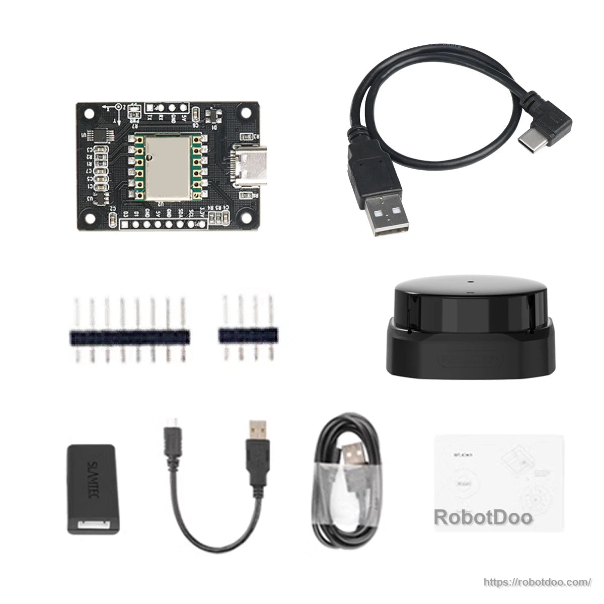
- 10-axis IMU inertia navigation module (without shell)
- 10-axis IMU inertia navigation module (with metal shell)
- 10-axis IMU inertia navigation module + GPS & Beidou positioning module
- 10-axis IMU inertia navigation module + MS200 lidar
- 10-axis IMU inertia navigation module + SLAMTEC S2L lidar
Indoor Navigation Kit Lidar Comparison (MS200 vs SLAMTEC S2L)
| Item | MS200 Lidar | SLAMTEC S2L Lidar |
| Ranging principle | TOF ranging | TOF ranging |
| Sampling frequency | 4500 Hz | 32000Hz |
| Scanning frequency | 7Hz - 15Hz (adjustable) | 15Hz |
| Resistance to environmental light | 40Klux | 80Klux |
| Size | 37.7*37.5*33mm | 77*77*38.9mm |
| Weight | 40g | 190g |
| Ranging radius | 0.03m - 12m | 0.05m - 18m |
| Driving method | Built-in brushless motor | Built-in brushless motor |
| ROS support | Support ROS1 / ROS2 | |
Software & Integration Notes
- ROS support notes: RViz visualization and ROS IMU pose visualization (yaw, pitch, roll)
- PC testing software: converts pose into a 3D model and presents real-time pose
- Parameter configuration can be adjusted in PC software and saved to flash (with automatic power-down data saving)
- STM32 calculation routines: supports linking with STM32 solution data and displaying current IMU data and posture angles
- Arduino calculation routines: outputs 9-axis raw data, angular velocity, angles, and other information via Arduino IDE serial monitor (minimal wiring)
Applications
- ROS1/ROS2 robot attitude measurement and pose estimation
- Robot navigation data acquisition (Euler angles, quaternion, pressure/height); GNSS/GPS-assisted fusion when connected
- Robotics R&D on PC, Raspberry Pi, NVIDIA Jetson, and STM32-based controllers
Video
Details
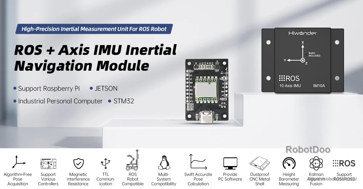
IM10A combines a 10-axis sensor set with ROS-oriented output for stable attitude and navigation data at up to 200Hz.
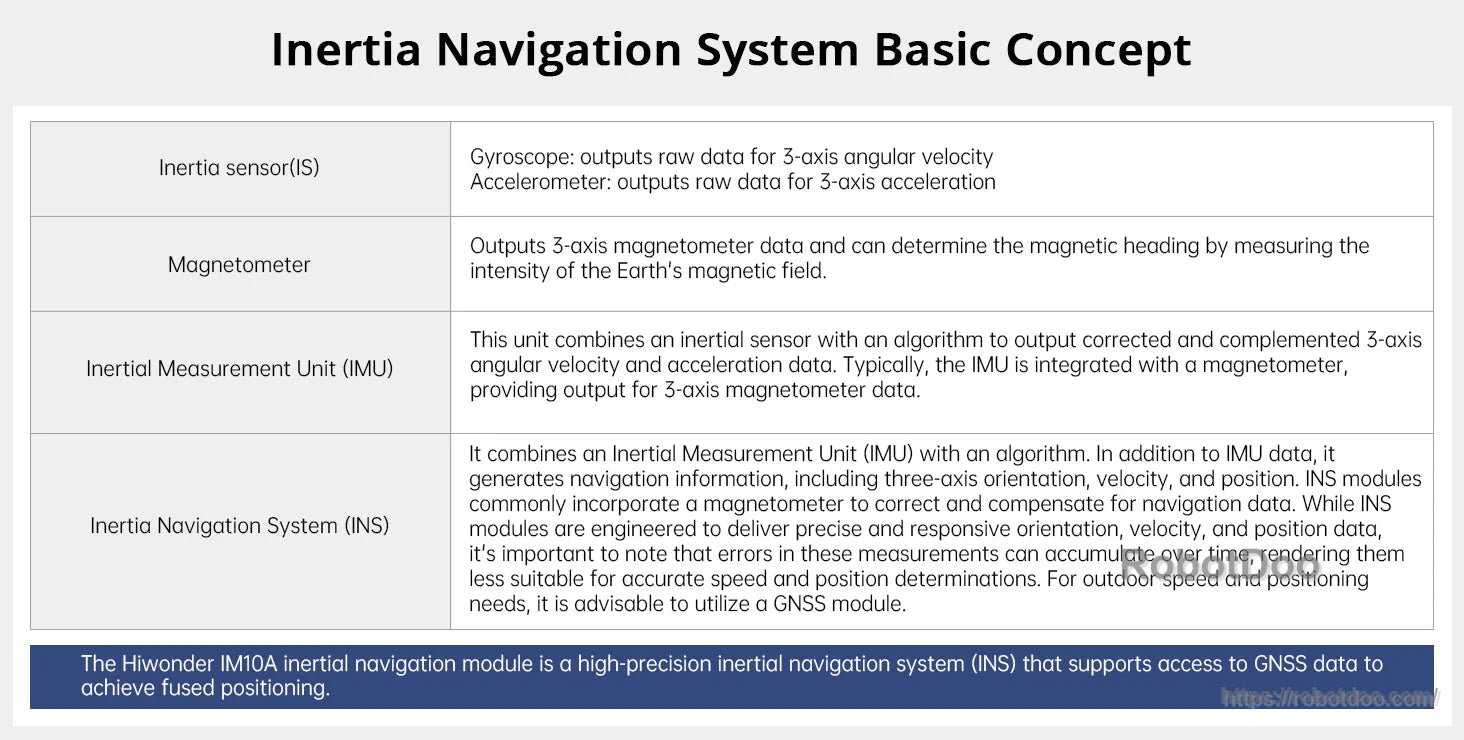
Sensor fusion merges gyro, accelerometer and magnetometer inputs to deliver corrected attitude and navigation information.
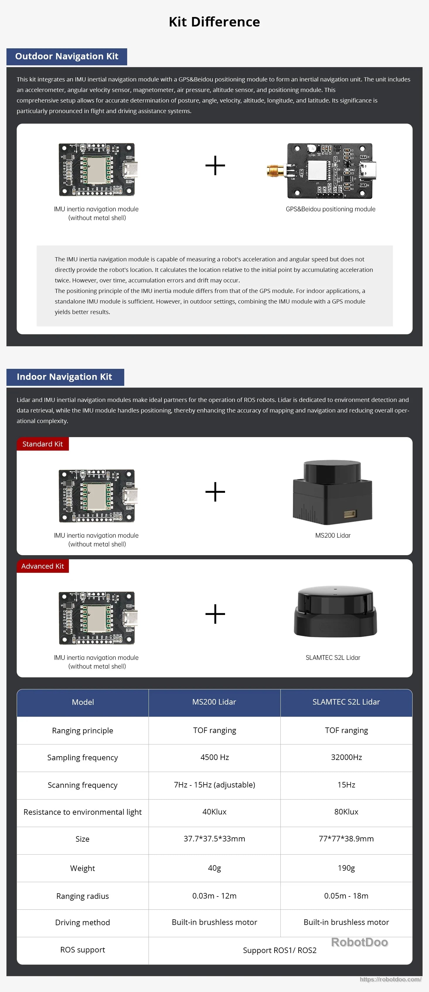
Choose a configuration that matches your stack—standalone IMU or a setup that accepts external positioning inputs like GPS/GNSS.
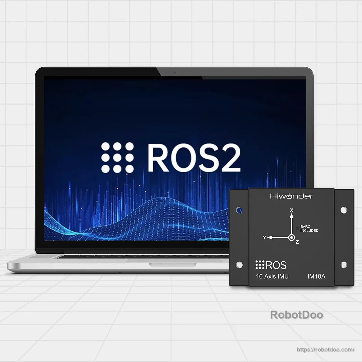
Designed for quick integration into ROS2 projects via common PC and SBC development workflows.

High update rates and a wide baud-rate range help keep motion data responsive for control and logging.
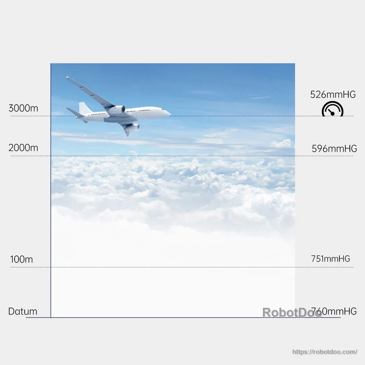
The onboard barometer provides air-pressure and altitude data for applications that benefit from height estimation.
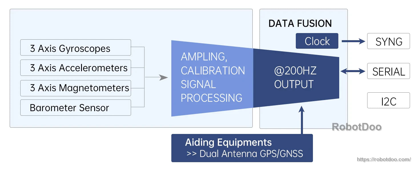
Multiple interfaces support flexible wiring, with optional NMEA GPS/GNSS input for integrated navigation fusion.
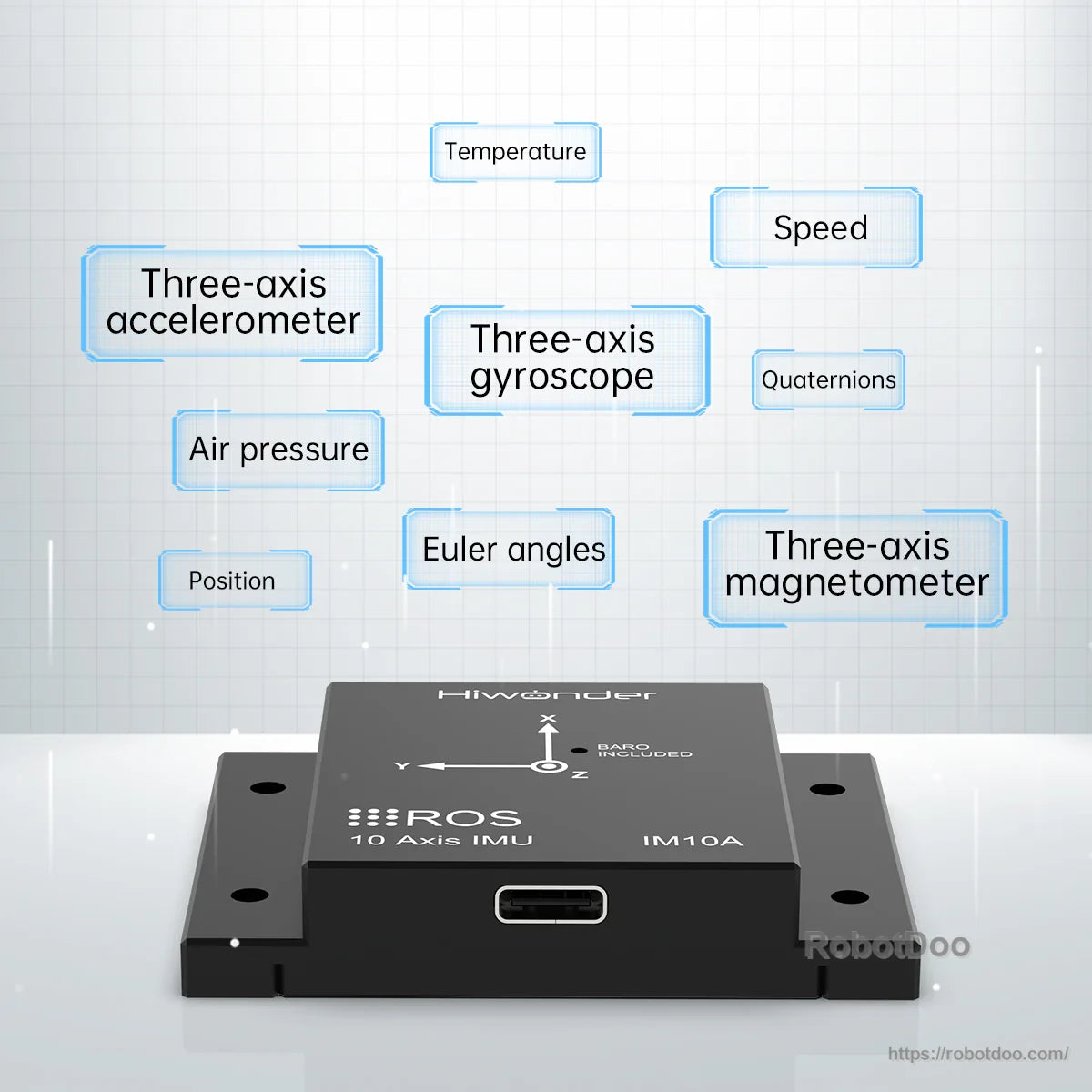
Outputs include acceleration, angular velocity, magnetic field, Euler angles and quaternions alongside pressure readings.
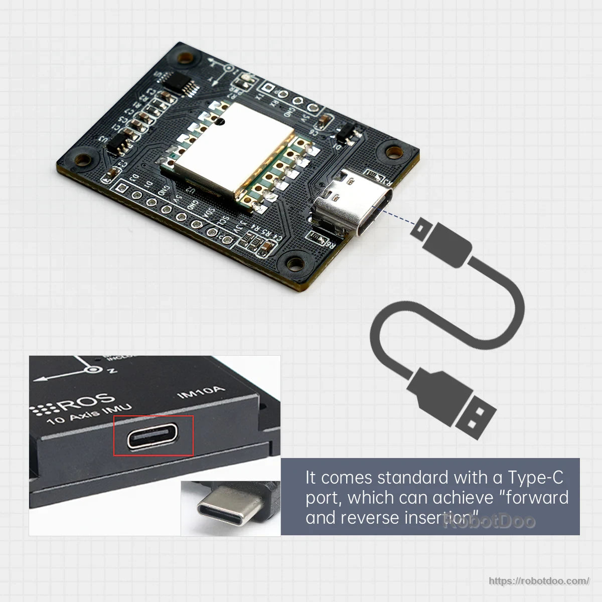
A reversible USB Type‑C port simplifies bench setup and field servicing.
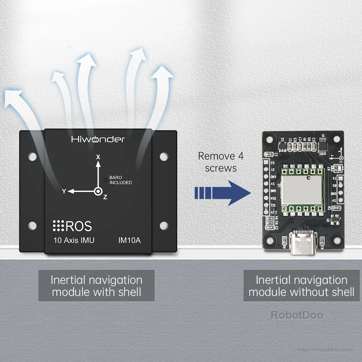
The removable CNC metal shell supports heat dissipation, while allowing access to internal pins when needed.
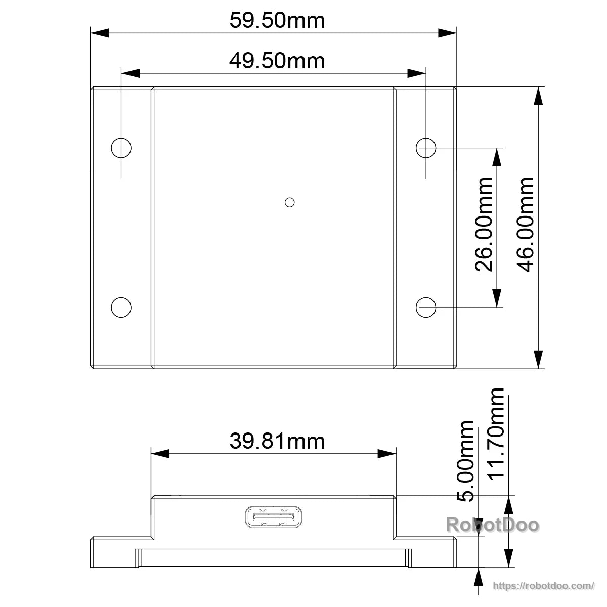
Mounting dimensions are provided to speed up bracket design and enclosure planning.
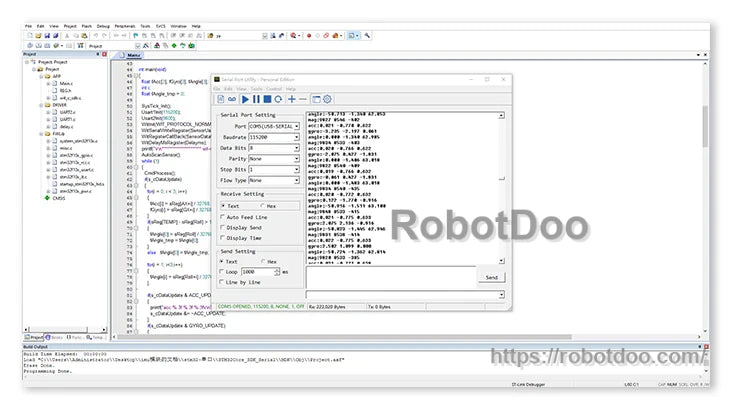
Windows tools enable real-time monitoring, data recording, and parameter tuning with settings saved to flash.
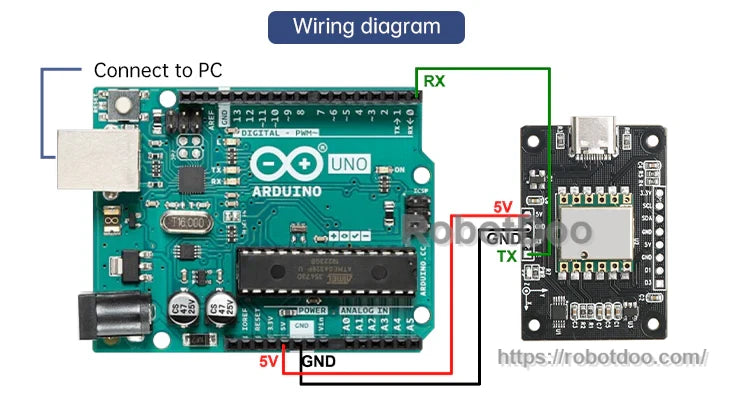
UART (TTL serial) wiring supports quick prototyping on microcontroller platforms.
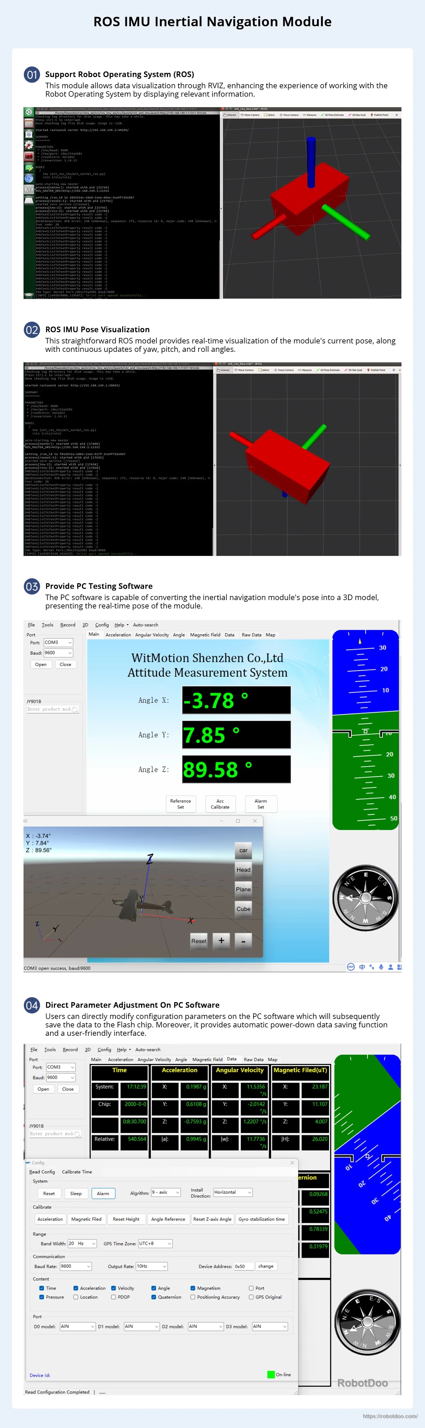
ROS packages and examples help verify topic output and visualize orientation during integration.
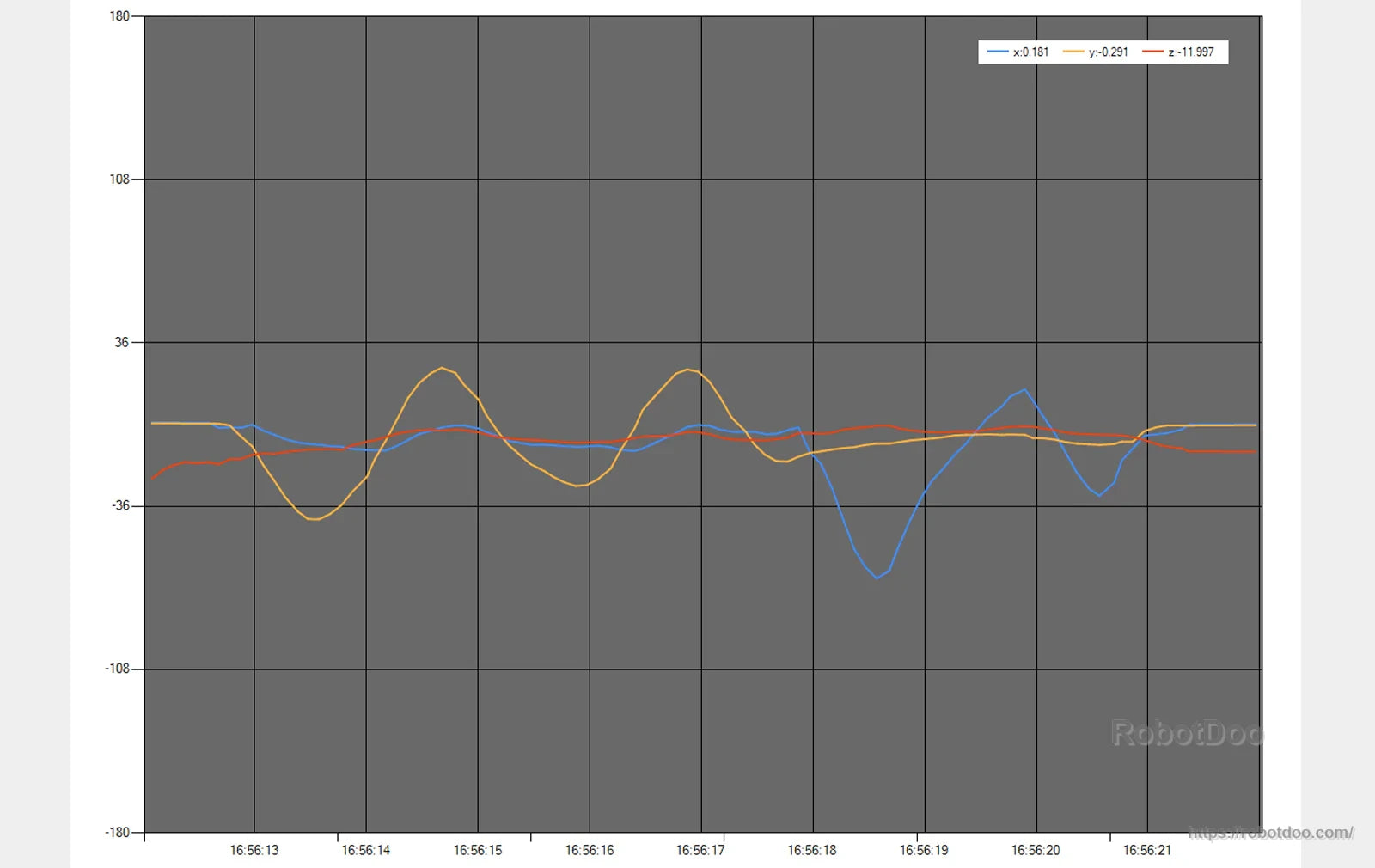
Live plotting makes it easier to validate calibration and spot noise or interference during testing.
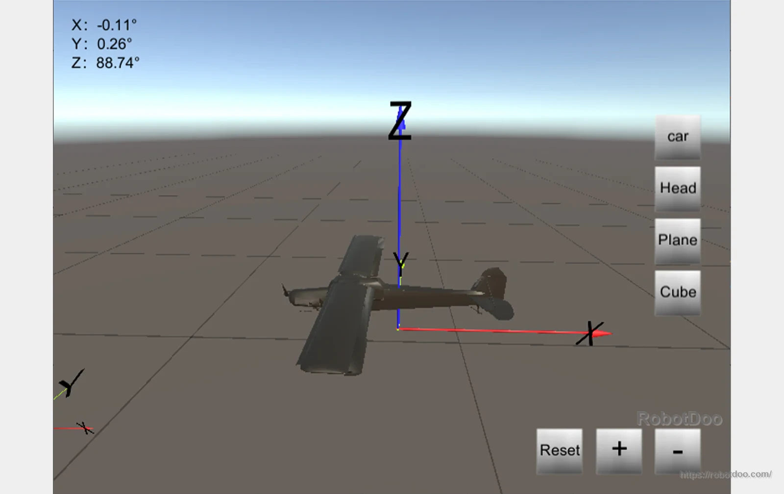
A 3D pose view provides an intuitive check of roll, pitch and yaw behavior during motion.
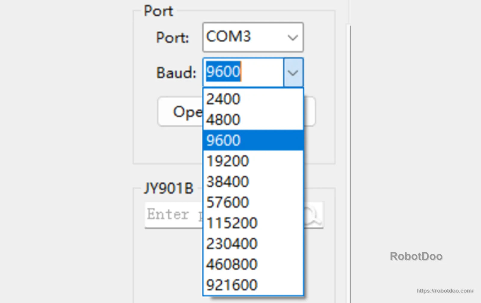
Baud rate can be adjusted to match your controller and data-rate requirements.
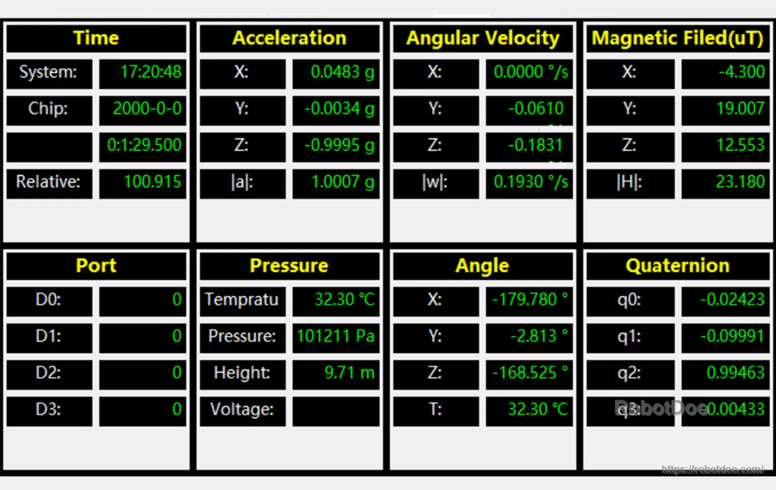
A consolidated dashboard view presents key sensor and fusion outputs in one place for quick validation.
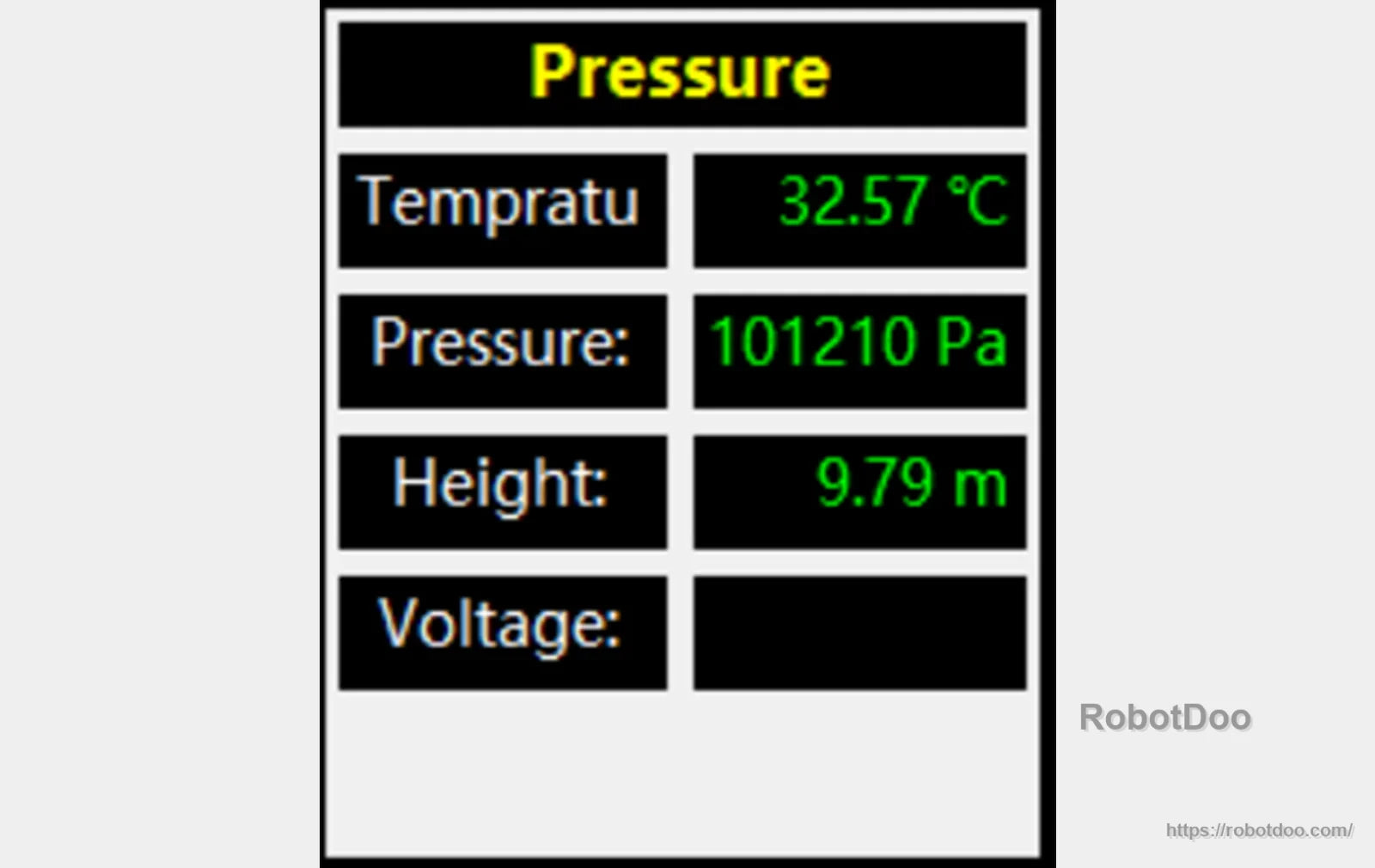
The module’s pressure sensor readout provides live temperature, pressure, and altitude values for monitoring in your robot project.
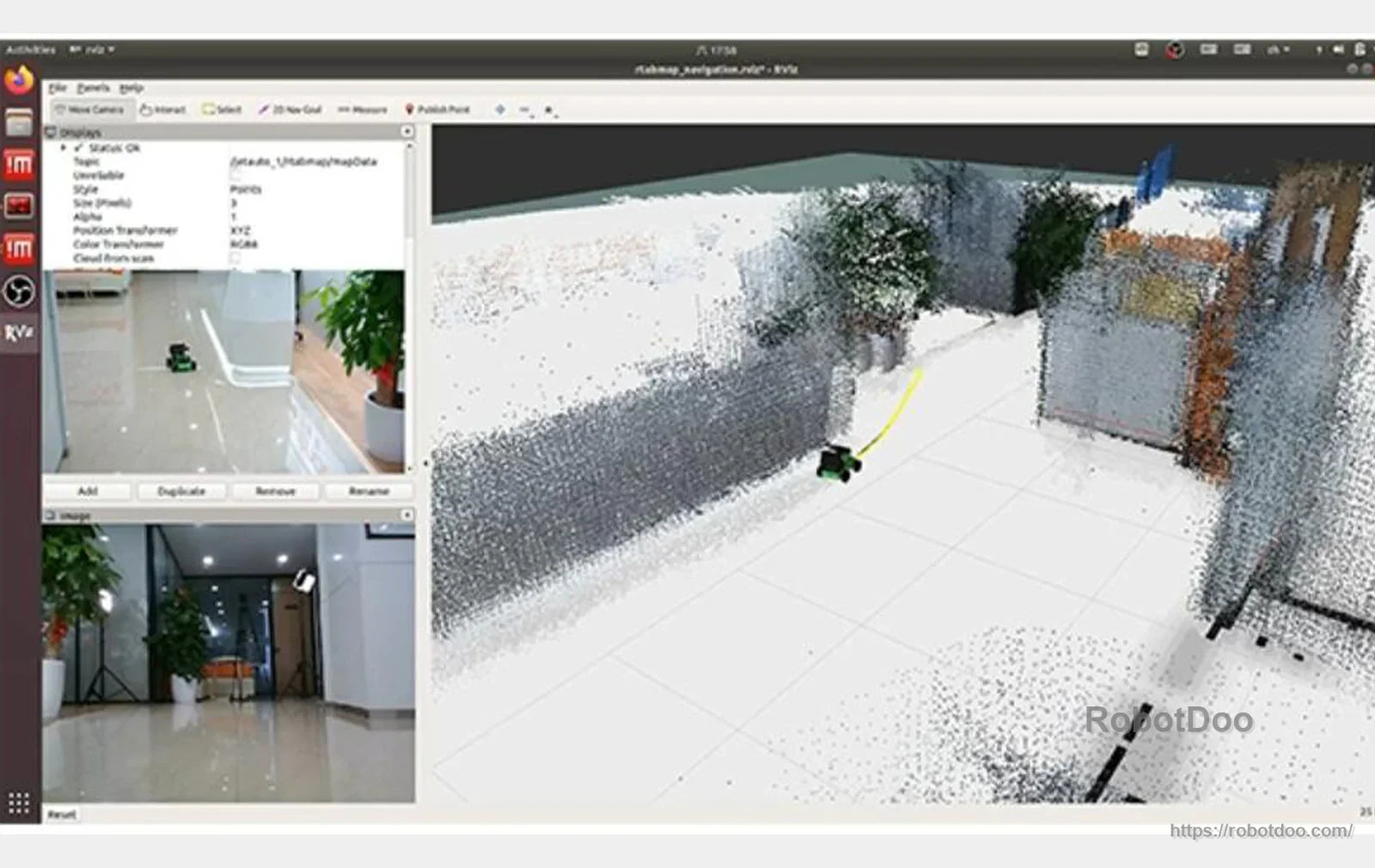
The IM10A module is commonly used in ROS setups where navigation and sensor data can be monitored in RViz during testing.

The IM10A IMU kit includes the sensor module, pin headers, and a 250mm USB Type-C data cable with straight-to-bent connectors for flexible routing.

The Hiwonder IM10A IMU package includes the metal-shelled module, pin headers, and a 250mm USB Type-C data cable with straight and bent connectors for flexible wiring.

The IM10A inertial navigation kit includes the IMU board, a USB Type‑C cable, a GPS module, an active antenna, and pin headers for straightforward integration.

The Hiwonder IMU module comes with pin headers, a USB Type-C cable, a serial port adapter, and connection cables for easier integration.

The Hiwonder IM10A IMU package includes pin headers and multiple cables/adapters to simplify integration and wiring in robot builds.