Product Description
The CHS-GM12-10BY is a miniature geared stepper motor with a metal gear reduction assembly and a two-phase, four-wire winding. Its compact construction is intended for integration into small motion-control mechanisms where installation space is limited.
Choose the gear ratio to match your required output speed, step increment and torque characteristics. The D-shaped output shaft provides a flat surface for compatible couplings.
Potential uses include compact positioning mechanisms, miniature robotic assemblies and camera movement prototypes. An external bipolar stepper driver is required. Review the dimensions, wiring and gear-ratio specifications before integration.
Key Features
- Compact motor and gearbox construction.
- Metal gear reduction assembly.
- Multiple gear ratios for mechanism selection.
- D-shaped shaft for compatible couplings.
- Attached motor leads and connector.
- External stepper-driver control.
Specifications
| Parameter | Specification |
|---|---|
| Model | CHS-GM12-10BY |
| Motor Type | Micro geared stepper motor |
| Nominal Voltage | DC 5.0V |
| Phases | 2 |
| Number of Wires | 4 |
| Gear Material | Metal |
| Motor and Gearbox Dimensions | Approximately 10 × 12 × 20mm, excluding output shaft |
| Output Shaft Length | 10mm |
| Output Shaft Profile | D-shaped |
| Output Shaft Diameter | Listed as 3mm; requires dimensional confirmation |
| D-Shaft Thickness | Listed as 2.5mm |
| Weight | Approximately 11g |
| Phase Current | 128mA per phase |
| Phase Resistance | 39Ω ±7% per phase |
| Phase Inductance | 14.3mH per phase |
| Referenced Driver IC | L6219 |
| Mounting Face | 10 × 12mm |
| Mounting Holes | 2 × M1.6 |
| Mounting Hole Spacing | 9mm |
| Lead Length | 75 ±10mm |
| Wire Specification | UL1571 AWG30 |
| Connector | Four-position, white housing |
| Connector Pitch | 1.25mm |
| Connector Reference | 51021-0400 |
| Excitation Sequence Shown | Two-phase-on, full-step |
| Starting Pulse Rate | Listed as >1200 PPS; requires confirmation |
| Response Pulse Rate | Listed as >900 PPS; requires confirmation |
| Encoder | Not specified |
| Driver Included | No, for the Motor Only configuration |
| Shaft Dimension Note | Mechanical drawing contains Ø3 and Ø4 markings; confirm output shaft dimensions before selecting a coupling |
Gear Ratio and Torque Specifications
| Nominal Gear Ratio | Actual Reduction Ratio | Output Step Angle | Holding Torque (kgf·cm) | Pull-Out Torque (kgf·cm) |
|---|---|---|---|---|
| 10:1 | 9.68:1 | 1.86° | 0.12 | 0.03 |
| 20:1 | 19.36:1 | 0.93° | 0.24 | 0.06 |
| 30:1 | 29.47:1 | 0.61° | 0.36 | 0.09 |
| 50:1 | 51.10:1 | 0.35° | 0.60 | 0.15 |
| 100:1 | 99.30:1 | 0.18° | 1.20 | 0.30 |
| 150:1 | 150.96:1 | 0.12° | 1.80 | 0.45 |
| 210:1 | 209.76:1 | 0.086° | 2.50 | 0.63 |
| 298:1 | 297.90:1 | 0.060° | Not separately specified | 0.90 |
| 380:1 | 379.16:1 | 0.047° | Not separately specified | 1.10 |
| Technical Note | Details |
|---|---|
| High-Ratio Torque Limit | The 298:1 and 380:1 entries share a maximum permissible torque notation of 3.0kgf·cm |
| Holding-Torque Limitation | The shared torque limit does not establish an individual holding-torque rating for either version |
| Step-Angle Interpretation | Output step angle represents the nominal angular increment, not positioning accuracy |
| Torque Test Conditions | Test speeds and load conditions are not specified |
| Ratio Notation | Reduction ratios are presented as input-to-output ratios |
Wiring Connections
| Wire Color | Winding Connection |
|---|---|
| White | A+ |
| Red | A− |
| Brown | B+ |
| Black | B− |
| Connector Pin | Wire Color |
|---|---|
| 1 | Brown |
| 2 | Black |
| 3 | White |
| 4 | Red |
| Wiring Note | Details |
|---|---|
| Connector Orientation | Check connector orientation before wiring |
| PCB Numbering | PCB solder-point numbering differs from connector pin numbering |
| Control Requirement | Use a compatible bipolar stepper driver |
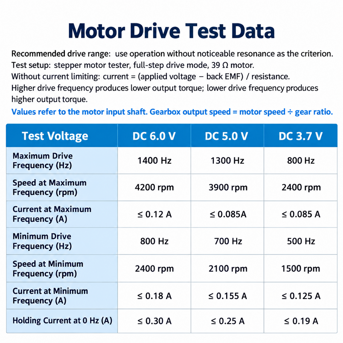
Drive Test Reference
| Test Parameter | DC 6.0V | DC 5.0V | DC 3.7V |
|---|---|---|---|
| Upper Drive Frequency | 1400Hz | 1300Hz | 800Hz |
| Motor Speed at Upper Frequency | 4200rpm | 3900rpm | 2400rpm |
| Current at Upper Frequency | ≤0.12A | ≤0.085A | ≤0.085A |
| Lower Drive Frequency | 800Hz | 700Hz | 500Hz |
| Motor Speed at Lower Frequency | 2400rpm | 2100rpm | 1500rpm |
| Current at Lower Frequency | ≤0.18A | ≤0.155A | ≤0.125A |
| Energized Stationary Current at 0Hz | ≤0.30A | ≤0.25A | ≤0.19A |
| Test Condition / Interpretation | Details |
|---|---|
| Drive Mode | Full-step |
| Winding Resistance | 39Ω |
| Current Limiting During Test | None |
| Speed Measurement | Motor speed before gear reduction |
| Current Measurement Basis | Not specified; test currents should not replace the phase-current specification |
| Voltage Interpretation | The 3.7V and 6V columns are test references, not separate rated-voltage options |
| Frequency and Torque | Available torque generally decreases as drive frequency increases |
| Drive-Setting Selection | Select settings that avoid noticeable motor resonance |
| Output-Speed Calculation | Motor speed ÷ actual reduction ratio |
| Performance Limitation | Test values do not establish guaranteed loaded output performance |
Package Includes
| Item | Quantity / Details |
|---|---|
| CHS-GM12-10BY Micro Geared Stepper Motor | 1, selected gear ratio |
| Motor Leads and Connector | Attached |
| Stepper Driver | Not included |
Applications
- Compact camera pan and positioning mechanisms
- Motorized selfie-stick mechanisms
- Smartphone camera tracking mechanisms
- Miniature robotic mechanisms
- Small robotic gripper mechanisms
- Compact printing and feed mechanisms
- Small motion-control prototypes
Suitability depends on the mechanism’s load, speed, duty cycle, driver settings and mounting requirements.
FAQ
Is this a stepper motor or a DC gear motor?
This is a geared stepper motor. It requires a stepper driver to energize the windings in sequence and does not operate like a two-wire brushed DC gear motor.
Can this motor run directly from a power supply?
A power supply alone cannot produce controlled continuous rotation. Use a compatible bipolar stepper driver and controller, with settings matched to the winding specifications.
Which gear ratio should I choose?
Choose a lower reduction ratio when output speed is the priority. Choose a higher ratio when smaller output step increments are needed. Compare the gear-ratio and torque table with your mechanism’s requirements.
Does this geared stepper motor have a fixed RPM?
No. Motor speed depends on drive frequency, and output speed also depends on the actual reduction ratio. The calculation method is listed in the drive-test table.
What is the difference between nominal and actual gear ratios?
Nominal ratios are rounded selection labels. Use the actual reduction ratio in the specification table when calculating output speed.
What output shaft does this motor use?
It uses a D-shaped output shaft. The listed dimensions are included in the specification table, but the shaft diameter requires confirmation before selecting a coupling.
Does the motor include a driver or encoder?
The Motor Only configuration includes the motor and attached leads. A driver is required separately. No encoder is specified for this configuration.
Is holding torque the same as running torque?
No. Holding torque applies to the energized stationary motor. Available torque during motion depends on speed and drive conditions. Pull-out torque is listed separately in the gear-ratio table.